As the preferred method of anion analysis, ion chromatography technology has been applied in more and more fields, from traditional environmental protection and disease control industries to high-end fields, such as power plant , semiconductor industry, nuclear power , military industry, etc.
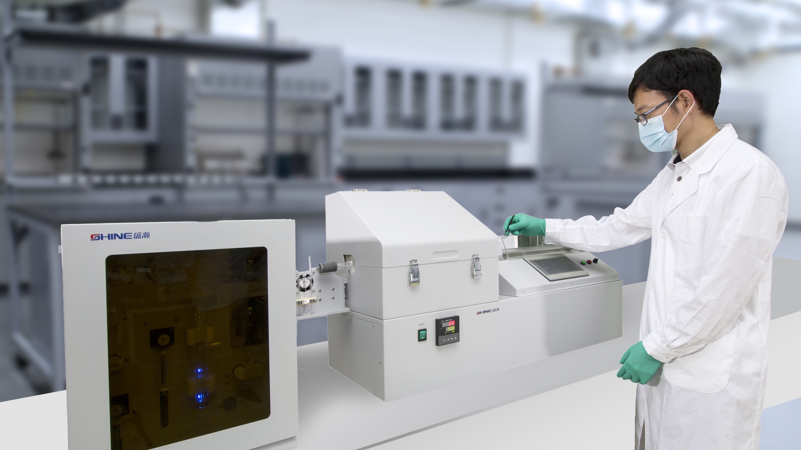
The analysis demand of high-end users is more stringent, which puts forward higher requirements for ion chromatography technology, among which the use of valve switching (also known as column switching) technology to analyze trace anions in samples has attracted more and more attention.
This paper introduces the basic pipeline connection of sample enrichment by using valve switching technology , hoping to provide you with a little help.
1. Main equipment and accessories:
Solenoid six-way valve: 2
High pressure infusion pump: 2 sets
Capture column: 1
Enrichment column: 1
Analysis column: 1
Ultra pure water: resistivity > 18.2M Ω· cm
Eluent generator: avoid the influence of impurity anion in reagent on analysis results
2.Pipeline connection
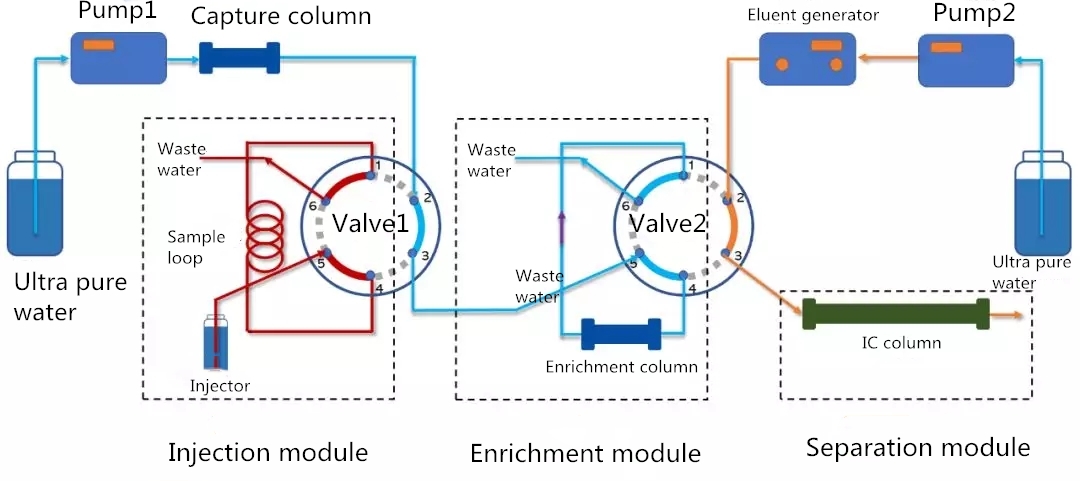
Fig. 1 Pipeline connection
Valve switching is mainly divided into three parts: injection module, enrichment module and separation module. The injection module is used to inject the samples into the large sample loop manually or automatically; the enrichment module is used to concentrate the components to be tested in the samples ; the analysis module is used to separate and detect the components to be tested after enrichment and concentration.
3.State analysis
(1)Injection state
As shown in the figure below, both solenoid valves are in the injection position.
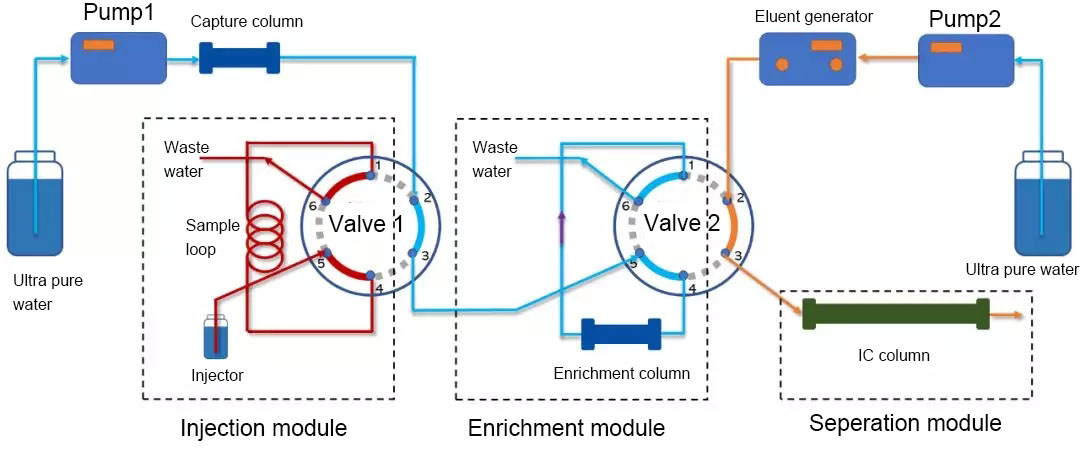
Fig. 2 Injection state
① Automatic injector / manual injector inject the sample into the sample loop;
② After the ultra pure water pumped by infusion pump 1 passes through the capture column, it enters into hole 2 of valve 1, flows out from hole 3, and is connected to hole 5 of valve 2. After passing through the capture column connected by hole 4 and 2, it is discharged from hole 6;
③ The infusion pump 2 pumps the ultra pure water into the eluent generator, and the eluent flows out to the chromatographic column through the 2 and 3 holes of the valve 2.
(2)Enrichment state
As shown in the figure below, valve 1 is switched to the analysis position and valve 2 is in the injection position.
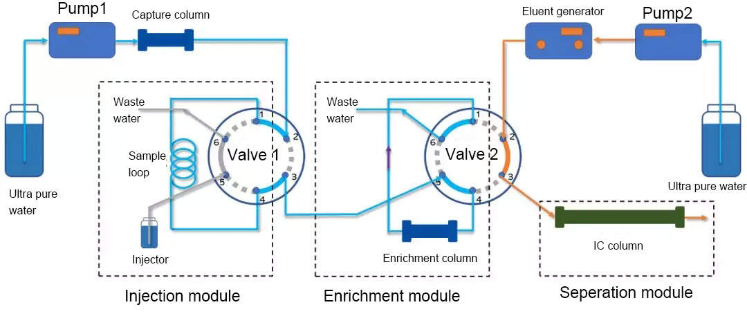
Fig. 3 Enrichment state
The sample to be analyzed in the sample loop of valve 1 is flushed out by pure water and enters the enrichment column of valve 2. Because pure water has no elution function, the components to be analyzed will be retained on the enrichment column . After a period of washing, all the samples to be analyzed in the sample loop enter the enrichment column to be enriched.
(3) Analysis state
As shown in the figure below, valve 1 is switched to the injection position and valve 2 is switched to the analysis position at the same time.
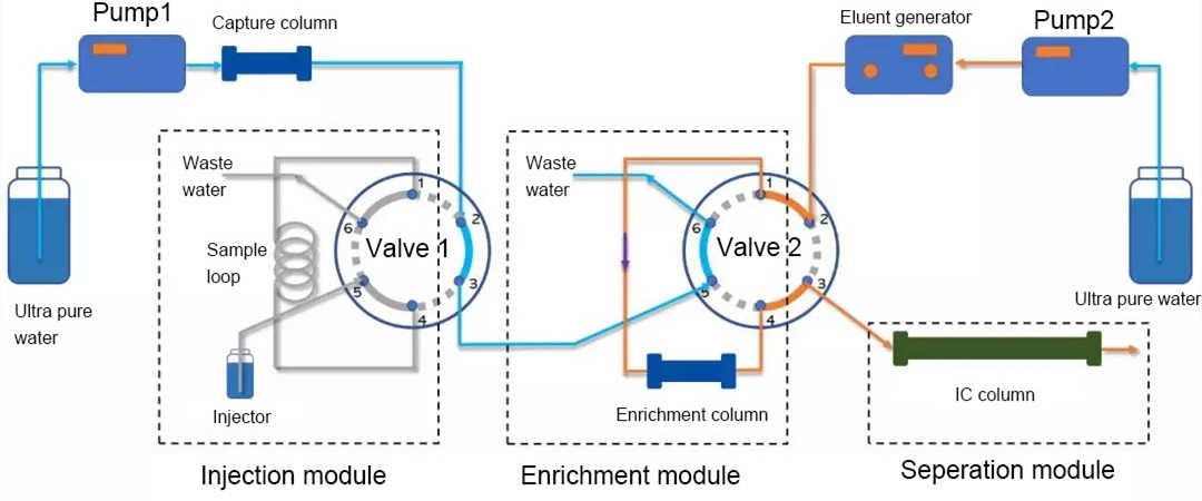
Fig. 4 Analysis Status
① After the sample is flushed out of the sample loop by valve 1, it will be switched to the sample injection position to prepare for the next sample analysis;
② The eluate produced by the eluate generator will pass through hole 2, 1, 4 and 3 of valve 2 in turn, and the adsorbed and concentrated components on the enrichment column will be flushed into the IC column for separation.
(4) injection state (reset to the position shown in Fig. 2)
Both valve 1 and valve 2 are in the injection position. After completing the analysis of one sample, valve 2 switches from the analysis position to the injection position, and the system enters the injection state, waiting for the next analysis process.
4.Precautions
(1) The valve switching technology requires more than two sample injection valves, so the switching time between the valves needs to be accurately controlled, otherwise the data may be low due to sample loss.
(2) At present, the commonly used suppressor is the self regeneration electrolysis micro membrane suppressor. Generally, the water used in the electrolysis process comes from the conductivity detector and flows back. In the trace ion analysis process, the anions in the return water may cause greater interference. Therefore, it is recommended to use the external water suppression mode. At this time, an additional infusion pump is needed.